
Last updated:
Linking outlets, switches, panels and circuits on the plan to the install
Key takeaways:
- Electrical plans use standardized symbols on the floor plan.
- They show outlets, switches, lighting, and panel and circuit information.
- Curved lines link switches to the fixtures they control.
Electrical plans are among the most symbol-dense drawings in a construction set, and for good reason: they define where power, lighting, and low-voltage systems go throughout a building. To someone unfamiliar with the conventions, an electrical plan can look like a scatter of cryptic marks — but each symbol has a precise meaning, and once you learn to read them, the plan tells a clear story of how a building is wired. This guide explains how to read electrical plans and their symbols.
Understanding electrical drawings helps owners verify their needs are met and helps tradespeople and students build a foundational skill.
What an electrical plan shows
An electrical plan is a floor plan overlaid with the building’s electrical systems — the outlets, switches, light fixtures, panels, and circuits that deliver and control power. Rather than showing walls and rooms in detail, it uses the floor plan as a background and populates it with electrical symbols positioned where each device goes. Reading it tells you where every receptacle, switch, and fixture is located, what controls what, and how the systems are organized. Larger projects separate power, lighting, and low-voltage systems onto different sheets for clarity.
Because electrical work involves safety and code compliance, these drawings are precise and heavily reliant on their legend, which defines every symbol used.

Common electrical symbols
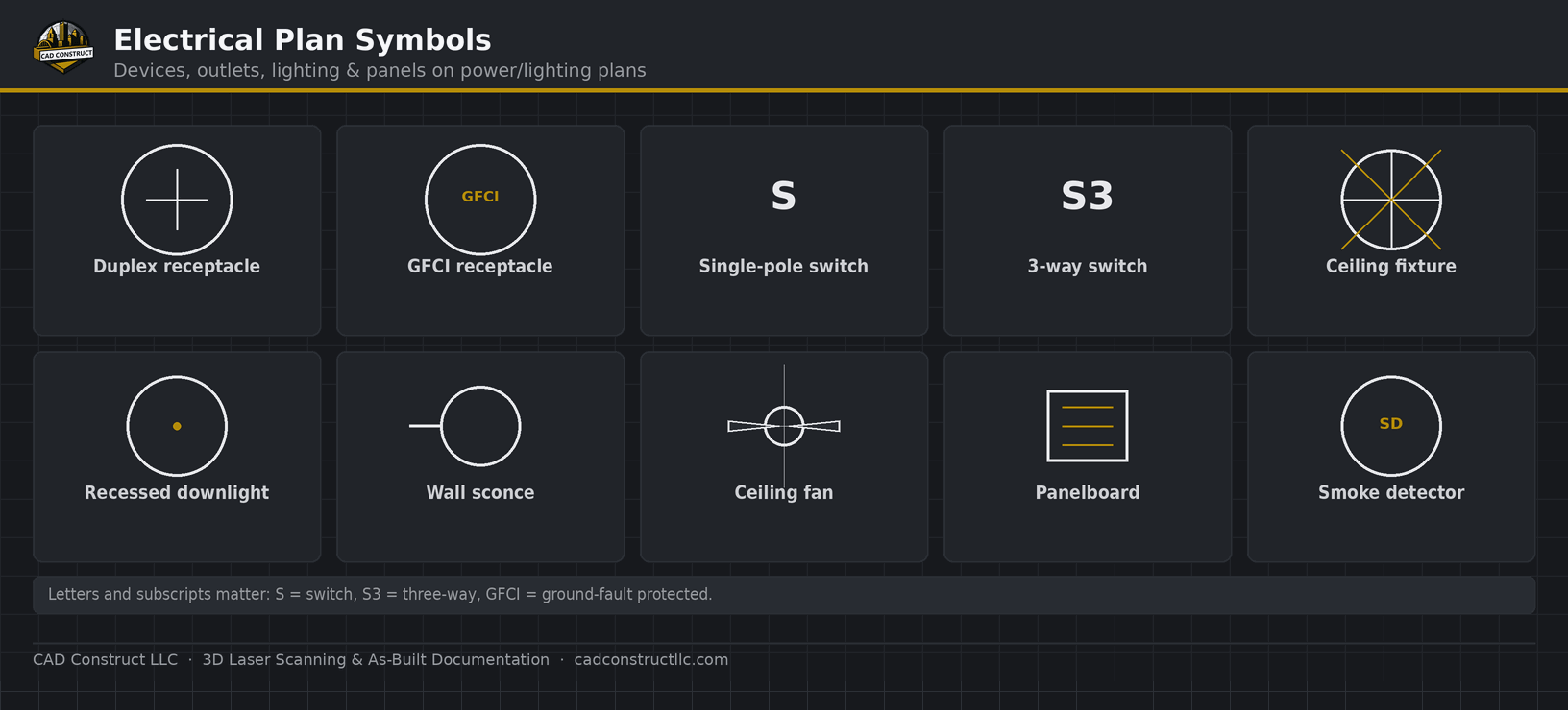
Electrical plans use a standardized set of symbols you will encounter constantly:
- Receptacles (outlets) — shown as circles with lines; a duplex outlet, a dedicated outlet, and a ground-fault outlet each have distinct marks.
- Switches — marked with an “S,” with variations for three-way, four-way, and dimmer switches.
- Light fixtures — circles or specialized shapes for ceiling lights, recessed cans, wall sconces, and fluorescent fixtures.
- Ceiling fans, smoke detectors, and thermostats — each with a recognizable symbol.
- Panels and disconnects — shown as rectangles marking electrical panels and equipment.
- Data, phone, and TV outlets — low-voltage symbols for communication points.
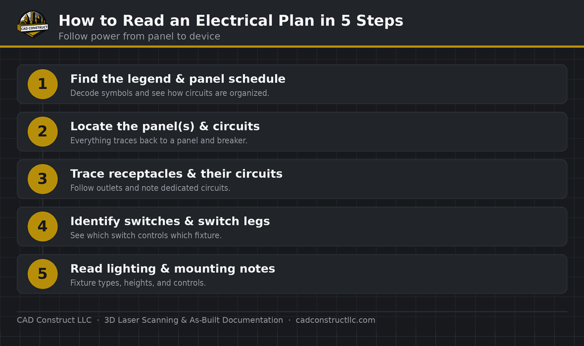
The legend on the electrical sheets defines exactly which symbols the set uses, so it is the first thing to consult when reading an electrical plan.

Reading switch-to-fixture connections
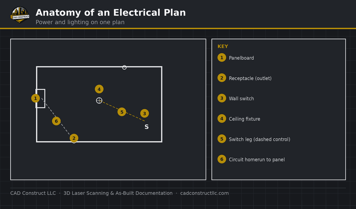
One of the most useful things an electrical plan communicates is what controls what. Curved lines called “switch legs” connect switches to the fixtures they operate, showing which switch turns on which light. A three-way switch arrangement — two switches controlling one fixture from different locations — is indicated by the switch symbols and the connecting lines. Reading these connections tells you how the lighting will actually work in a room, which is one of the most practical pieces of information on the drawing.
Understanding circuits and panels
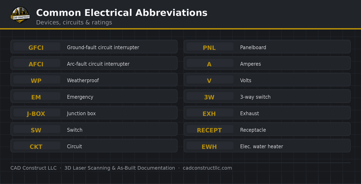
Electrical plans organize devices into circuits, each protected by a breaker in a panel. Circuit numbers and homerun symbols (arrows indicating the wiring path back to the panel) show how devices are grouped and fed. A panel schedule — usually a table on the electrical sheets — lists each circuit, its breaker size, and what it serves. Reading the panel schedule alongside the plan tells you how the electrical load is distributed and how the system is organized, which is essential for understanding capacity and for any future changes.
Power, lighting, and low-voltage plans
On all but the smallest projects, electrical information is split across separate plans to keep each readable. The power plan shows receptacles and equipment connections; the lighting plan shows fixtures and switching; the low-voltage or systems plan shows data, communications, security, and fire-alarm devices. Knowing which plan you are reading helps you focus on the relevant symbols and find the information you need. As always, each plan’s legend defines its symbols precisely.
How electrical plans connect to the set
Electrical plans coordinate with the architectural plans (which define the spaces and ceilings), the reflected ceiling plans (which show fixture layouts from the ceiling’s perspective), and the mechanical plans (since equipment needs power). Reading them together ensures the electrical design fits the building. For existing buildings undergoing renovation, accurate documentation of current conditions supports electrical planning, and 3D laser scanning combined with Scan-to-BIM helps capture and coordinate existing systems.
Related blueprint reading guides
- How to Read Construction Blueprints
- How to Read Plumbing Blueprints
- How to Read HVAC & Mechanical Drawings
- How to Read a Reflected Ceiling Plan
- Blueprint Symbols & Legends Explained
Related work: See real 2D drawings and CAD deliverables in our CAD portfolio.
Frequently asked questions
Why do electrical plans have so many symbols?
Electrical systems include many device types — outlets, switches, fixtures, data points, and more — each needing a distinct symbol so the plan can show exactly what goes where. The density reflects the complexity of a building’s wiring, and the legend defines every symbol so nothing is ambiguous.
How do I tell which switch controls which light?
Curved connecting lines, called switch legs, link each switch to the fixtures it controls. Following these lines from a switch to a fixture shows you exactly what turns on what, including three-way arrangements where two switches control the same light.
What is a panel schedule?
A panel schedule is a table listing each circuit in an electrical panel, its breaker size, and what it serves. Read alongside the plan, it shows how the building’s electrical load is organized and distributed, and it is essential for understanding capacity and planning changes.
Electrical plans map a building’s power, lighting, and low-voltage systems using a precise symbol language. Learn the common symbols, use the legend, follow switch-to-fixture connections, and read the panel schedule, and the dense marks on an electrical plan resolve into a clear picture of how a building is wired.
What is a homerun on an electrical plan?
A homerun is the wiring path that runs from a group of devices back to the electrical panel, usually shown as an arrow with a circuit number. It indicates which circuit the devices belong to and traces their connection to the panel. Reading homeruns alongside the panel schedule shows how devices are grouped onto circuits and how the load is organized.
Do electrical symbols vary between projects?
The core symbols are widely standardized, so outlets, switches, and common fixtures look familiar across most sets. However, some symbols vary by firm or project, and specialized devices may use custom marks — which is exactly why every electrical set includes a legend defining its symbols. Consulting that legend ensures you read each project’s symbols correctly.
Can electrical drawings be created for a building without them?
Yes. When a building lacks electrical documentation, its visible devices, panels, and equipment can be captured and documented to produce accurate drawings of the existing system. This is valuable for renovations and for facility management, giving the team a reliable record of how the building is powered rather than relying on guesswork.
What is an electrical plan?
A floor plan overlay showing outlets, switches, lighting, panels, and circuits using standard electrical symbols.
How are outlets shown on an electrical plan?
Receptacles are usually shown as a circle with lines; special types such as GFCI, 220-volt, or floor outlets have distinguishing marks.
How are switches indicated?
With an S, sometimes with a subscript like S3 for a three-way switch, placed near the door or area they serve.
What does the curved dashed line between a switch and a light mean?
It is a control line showing which fixture that switch operates, not the actual wire route.
Related blueprint reading guides
- USIBD Level of Accuracy (LOA), explained
- How to Read Construction Blueprints — full guide
- How to Read Plumbing Blueprints
- How to Read HVAC & Mechanical Drawings
- How to Read Structural Drawings
- How to Read a Reflected Ceiling Plan
- Blueprints vs. 3D Models & BIM
Turning these drawings into a field-verified digital record? See our scan-to-BIM services and as-built documentation across Pittsburgh & Western PA, or request a quote.


0 Comments