
Last updated:
Linking ductwork, equipment and diffusers to how air moves through the building
Key takeaways:
- Mechanical plans show ducts, equipment, diffusers, and controls.
- Ductwork is drawn to scale with size and airflow noted.
- Equipment schedules specify each unit’s capacity and details.
Mechanical drawings — most often called HVAC drawings, for heating, ventilation, and air conditioning — show how a building is heated, cooled, and ventilated. They map the equipment, ductwork, piping, and controls that keep a building comfortable, and they use their own set of symbols and conventions. Learning to read HVAC and mechanical drawings reveals a system that is largely hidden above ceilings and inside chases. This guide explains how to read HVAC and mechanical drawings.
Whether you are an owner, a facility manager, a tradesperson, or a student, understanding mechanical drawings demystifies one of a building’s most important and most concealed systems.
What mechanical drawings show
Mechanical drawings document the equipment and distribution systems that condition a building’s air. They typically include mechanical floor plans showing ductwork and equipment layouts, equipment schedules listing the units and their specifications, and sometimes diagrams and details for piping and controls. Together they communicate how conditioned air and, in some systems, heating or cooling water are produced and distributed to each space. Because HVAC is mostly concealed above ceilings and within mechanical rooms and shafts, these drawings are the primary way to understand it.
As with other technical drawings, mechanical plans depend on a legend that defines the symbols, line types, and abbreviations, which is where reading begins.
Reading ductwork
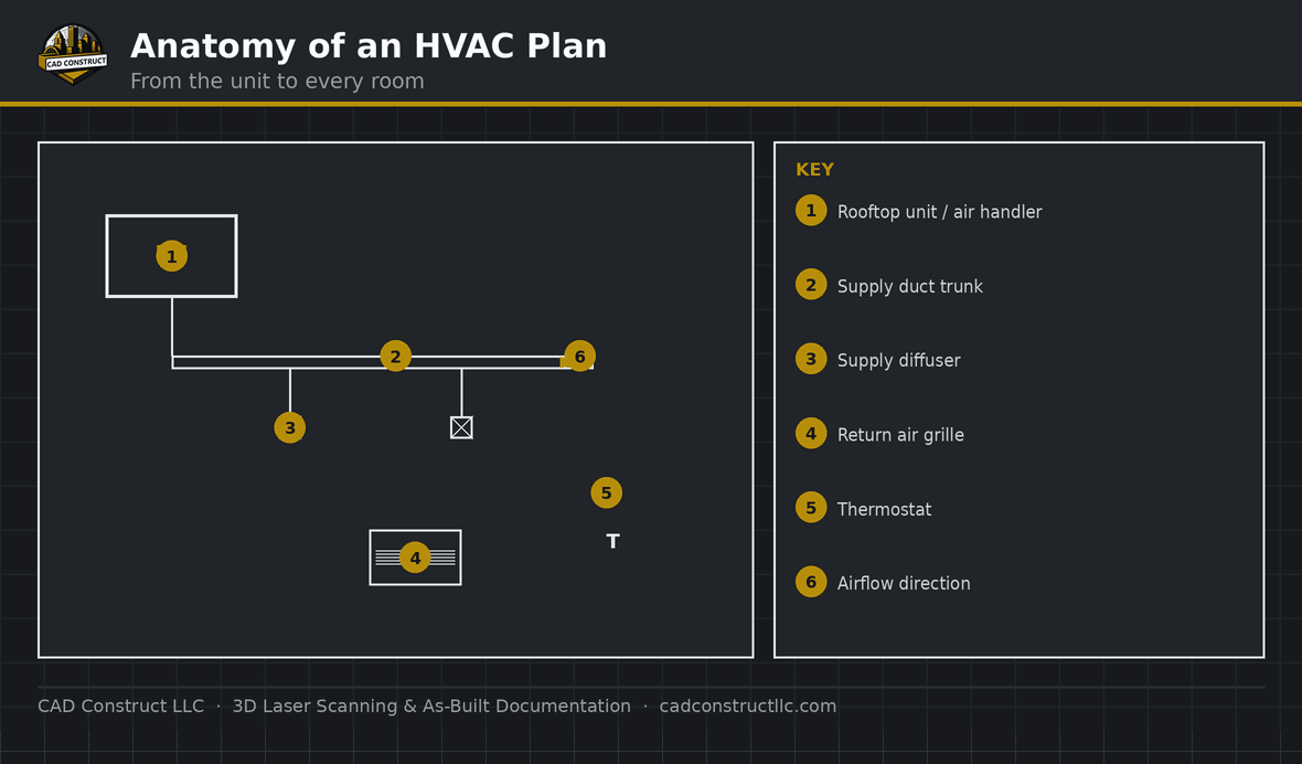
The most visible feature of many mechanical plans is the ductwork — the network of ducts that carries air through the building. Supply ducts deliver conditioned air to spaces, and return ducts carry air back to the equipment. Ducts are drawn as double lines showing their width, often with the size noted (such as 12×8, meaning twelve inches by eight inches). Diffusers and registers — the grilles where air enters or leaves a room — are shown with symbols at the duct ends. Reading the ductwork tells you how air moves through the building, from the equipment out to each space and back.
Understanding equipment and schedules
Mechanical systems center on equipment — furnaces, air handlers, rooftop units, condensers, boilers, and more — shown on the plan with symbols or outlines at their locations. An equipment schedule, usually a table on the mechanical sheets, lists each unit with its type, capacity, and specifications. Reading the schedule alongside the plan tells you what each piece of equipment is and what it does. This pairing of a symbol on the plan with a detailed line in the schedule is central to understanding a mechanical system’s capacity and organization.
Diffusers, registers, and airflow
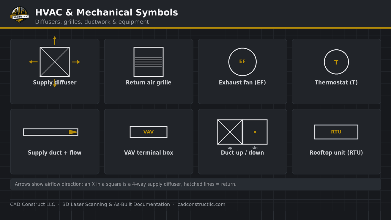
Where air enters and leaves each room is shown by diffuser and register symbols, often with the airflow quantity noted in cubic feet per minute (CFM). Supply diffusers deliver conditioned air, return grilles pull air back, and exhaust points remove air from spaces like bathrooms and kitchens. Reading these symbols and their airflow values tells you how each space is ventilated and conditioned. The pattern of supply and return points reveals how the designer intends air to circulate through a room, which affects comfort and performance.
Piping in mechanical systems
Beyond air, many systems distribute heating or cooling using water or refrigerant, and mechanical drawings show this piping with distinct line types. Hydronic systems circulate hot or chilled water to units through supply and return piping; refrigerant lines connect condensers to indoor units. As with plumbing, different line types distinguish the systems, defined in the legend. Reading the piping tells you how thermal energy is distributed, complementing the ductwork that distributes the air itself. On larger commercial and industrial projects, this piping can be extensive and is a major part of the mechanical design.
How mechanical drawings connect to the set
Mechanical drawings coordinate closely with the other disciplines because HVAC systems occupy significant space, especially above ceilings. They must fit around structural beams, coordinate with electrical and plumbing in the ceiling plenum, and align with the reflected ceiling plans that show diffuser locations. Reading mechanical plans alongside these other drawings reveals how the systems share space and where conflicts might occur. This is exactly the kind of coordination that Scan-to-BIM and clash detection address, and where accurate existing-conditions capture is essential for renovations.
Types of mechanical drawings in the set
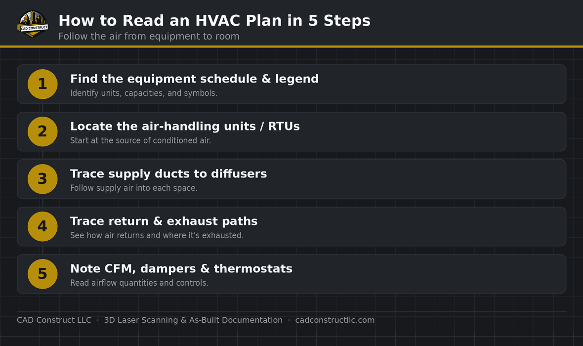
Mechanical documentation is usually filed under the “M” sheet series, and knowing the running order helps you find information quickly. The set typically opens with an M0 or M1 sheet carrying the mechanical legend, abbreviations, and general notes, then moves into floor-by-floor mechanical plans that show ductwork and equipment in place. Behind the plans sit the mechanical schedules that list every piece of equipment, followed by large-scale mechanical details and, on larger projects, a controls or sequence-of-operations sheet describing how the system is meant to run.
Reading the sheets in that sequence — legend first, then plans, then schedules and details — keeps you from guessing at a symbol you could have looked up in thirty seconds. When a plan references a detail with a bubble callout, the number tells you which detail sheet to jump to, and the schedules tie every tag on the plan back to a specific model, capacity, and electrical requirement so nothing is left to interpretation on site.
Reading the mechanical legend and common abbreviations
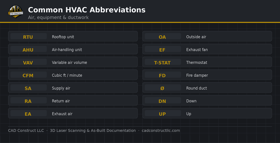
Mechanical drawings lean heavily on abbreviations, which is exactly why the legend is the most important sheet in the set. Airflow is labeled by function: SA for supply air, RA for return air, EA for exhaust air, and OA for outside air, each usually shown with its own line type or arrow style. Equipment carries standard tags too — RTU for a rooftop unit, AHU for an air-handling unit, FCU for a fan-coil unit, VAV for a variable-air-volume box, and EF for an exhaust fan.
Once those codes are familiar, a dense mechanical plan becomes readable: you can trace supply air from the air handler, through the VAV boxes, and out to the diffusers, then follow the return path back to the unit. Pairing each abbreviation with its schedule tag — for example, “RTU-1” — lets you confirm precisely which unit serves which zone, how much air it moves, and what electrical service it needs. Cross-checking the plan tag against the schedule is the single fastest way to avoid misreading the design intent.
Common mistakes when reading mechanical drawings
The most frequent error is reading a duct size as a diameter when it is actually a rectangular dimension — a “12×8” duct is 12 inches by 8 inches, not a 12-inch round. Another is overlooking the difference between single-line and double-line duct representation; single-line drawings communicate routing and sizing but not the true width the duct will occupy in a tight ceiling cavity. A third is reading the mechanical plan in isolation: diffuser and grille locations must line up with the reflected ceiling plan, and equipment weights, curbs, and roof openings must be verified against the structural drawings before anything is ordered.
How 3D laser scanning improves mechanical coordination
Mechanical systems are the most space-hungry trade above any ceiling, and they are rarely installed exactly as originally drawn. That is why field-verified existing conditions matter so much on renovations and retrofits. A 3D laser scan captures ductwork, piping, and structure exactly as they sit today, so designers can route new HVAC around real obstructions instead of relying on outdated record drawings. Feeding that point cloud into a scan-to-BIM model lets every trade run clash detection before a single duct is fabricated.
For tenant fit-outs and equipment replacements, this is the difference between a clean install and a field full of change orders. If you are planning mechanical work in an existing building, CAD Construct can document the space first — get in touch or review our pricing to see how field verification fits your project and budget.
Related blueprint reading guides
- How to Read Construction Blueprints
- How to Read Electrical Plans & Symbols
- How to Read Plumbing Blueprints
- How to Read a Reflected Ceiling Plan
- How to Read Structural Drawings
Related work: See real 2D drawings and CAD deliverables in our CAD portfolio.
Frequently asked questions
What does a duct size like “12×8” mean?
It gives the duct’s cross-sectional dimensions — twelve inches by eight inches in that example. Duct sizes are noted on the plan so you know how large each run is, which relates to the volume of air it carries. Larger ducts carry more air; sizes reduce as the run branches toward individual spaces.
What is CFM on a mechanical drawing?
CFM stands for cubic feet per minute, a measure of airflow. Diffusers and registers are often labeled with a CFM value indicating how much air they deliver or return, which tells you how each space is ventilated and helps you understand the system’s design intent.
Why is HVAC coordination so important?
Because ductwork and equipment are large and share tight ceiling space with structure, electrical, and plumbing, coordination prevents conflicts where systems would otherwise collide. Reading the mechanical drawings with the other disciplines — or coordinating them in a BIM model — catches these clashes before construction.
HVAC and mechanical drawings map how a building is heated, cooled, and ventilated through ductwork, equipment, and piping. Learn to read the ductwork and its sizes, pair equipment symbols with schedules, interpret diffusers and airflow, and follow the piping, and the concealed mechanical systems of a building become clear.
<
p class=”post-cta”>
What do HVAC drawings show?
The heating, cooling, and ventilation layout — ductwork, air handlers, rooftop units, diffusers, and controls — on the floor plan.
How is ductwork represented?
As double lines drawn to scale showing width and depth, with size labels and sometimes airflow in CFM.
What is a diffuser or register on the plan?
A symbol marking where conditioned air enters as supply or leaves as return, often noted with neck size and CFM.
What is an equipment schedule?
A table listing each mechanical unit with its capacity, airflow, electrical needs, and model reference.
What does CFM mean?
Cubic feet per minute — the volume of air a duct or diffuser delivers, used to balance the system.
What are supply and return ducts?
Supply ducts push conditioned air into spaces, while return ducts pull room air back to the equipment.
How are thermostats and controls shown?
With a T symbol and control notes indicating zones and how the equipment is operated.
Renovating a mechanically complex building? CAD Construct LLC captures existing systems accurately with 3D laser scanning and supports coordination with Scan-to-BIM across Pittsburgh and Western Pennsylvania. Request a quote.
Related blueprint reading guides
- USIBD Level of Accuracy (LOA), explained
- How to Read Construction Blueprints — full guide
- How to Read Structural Drawings
- How to Read a Reflected Ceiling Plan
- How to Read Site & Plot Plans
- How to Read Floor Plans
- Blueprints vs. 3D Models & BIM
Turning these drawings into a field-verified digital record? See our 3D laser scanning in Pittsburgh and scan-to-BIM services across Pittsburgh & Western PA, or request a quote.


0 Comments