
Carrying a reader from the title block to the details, sheet by sheet
Last updated:
Key takeaways:
- Blueprints follow a consistent, learnable system of sheets, symbols, and scales.
- Read the general sheets first (title block, index, plans), then the details.
- The scale and legend are the keys to interpreting every line and note.
Construction blueprints can look intimidating the first time you unfold a set — a wall of lines, symbols, numbers, and abbreviations that seem to assume you already know the language. But blueprints follow a consistent, learnable system. Once you understand how a drawing set is organized and what the main components mean, you can read almost any set of construction documents with confidence. This beginner’s guide walks you through the fundamentals of reading construction blueprints from the ground up.
Whether you are a homeowner reviewing plans for a renovation, a new tradesperson, a student, or a property owner trying to understand what you are paying for, learning to read blueprints puts you in control of your project.

What blueprints actually are
A blueprint is a technical drawing that communicates exactly how something is to be built. The term dates back to an old reproduction process that produced white lines on a blue background, and although modern drawings are printed in black on white, the name stuck. Today “blueprints,” “construction drawings,” “plans,” and “construction documents” all refer to the same thing: the detailed set of drawings and specifications that guide a building project.
A complete set of blueprints is not a single page. It is an organized collection of drawings, each showing the building from a different viewpoint or focusing on a different system. Learning to navigate that organization is the first step to reading them well.

How a drawing set is organized
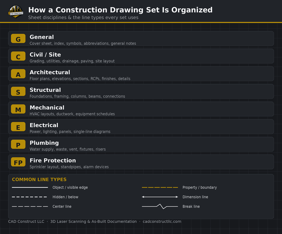
Construction documents are arranged in a logical order, usually grouped by discipline and labeled with a letter-and-number system. While conventions vary slightly, a typical set runs in this general sequence:
- Title / cover sheet — project name, address, an index of all drawings, and general information.
- A — Architectural — floor plans, elevations, sections, and details that define the layout and appearance.
- S — Structural — foundations, framing, beams, and columns that hold the building up.
- M — Mechanical (HVAC) — heating, ventilation, and air-conditioning systems.
- E — Electrical — power, lighting, and low-voltage systems.
- P — Plumbing — water supply, drainage, and gas lines.
- C — Civil — site work, grading, and utilities outside the building.
Each sheet is numbered within its discipline — A-101, A-102, S-201, and so on — so anyone on the project can quickly find the drawing they need. Getting comfortable with this “table of contents” logic makes the whole set far less overwhelming.

The title block: where to start on any sheet
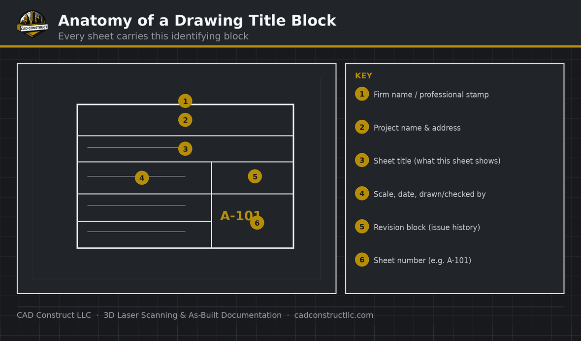
Every drawing sheet has a title block, usually along the right edge or bottom. It is the single most useful thing to read first, because it tells you what you are looking at. The title block typically includes the project name and address, the sheet title and number, the drawing scale, the date and revision history, and who prepared the drawing. Before studying the lines on a sheet, read its title block so you know the drawing’s purpose and, critically, its scale.

Understanding scale
Blueprints are drawn to scale, meaning a small measurement on paper represents a larger real-world distance. A common architectural scale is 1/4″ = 1′-0″, where a quarter inch on the drawing equals one foot in reality. Understanding scale is essential because it lets you determine real dimensions from the drawing. Most sets state the scale in the title block and beside each drawing, and many dimensions are written directly on the plan so you do not have to measure — but knowing the scale lets you check anything that is not labeled.
A scale ruler (or “architect’s scale”) makes reading scaled drawings easy, but the most important habit is to always confirm the scale before assuming a size, since different sheets in the same set can use different scales.

The main types of drawings
Once you can navigate the set, the next step is recognizing the main drawing types and what each shows. These are the views you will encounter most often:
- Floor plans — a view looking straight down, as if the building were sliced horizontally about four feet up. They show room layouts, walls, doors, windows, and dimensions. Floor plans are the drawings people read most.
- Elevations — flat, straight-on views of the building’s exterior (or interior walls), showing height, materials, and appearance.
- Sections — a view as if the building were sliced vertically, revealing what is inside walls, floors, and roofs.
- Details — close-up, large-scale drawings of specific conditions, like how a wall meets a foundation.
- Site plans — an aerial view of the whole property showing the building’s placement, setbacks, and site features.
Each of these deserves its own study, and later guides in this series cover them one by one. For now, simply recognizing which view you are looking at is a major step forward.

Symbols, lines, and abbreviations
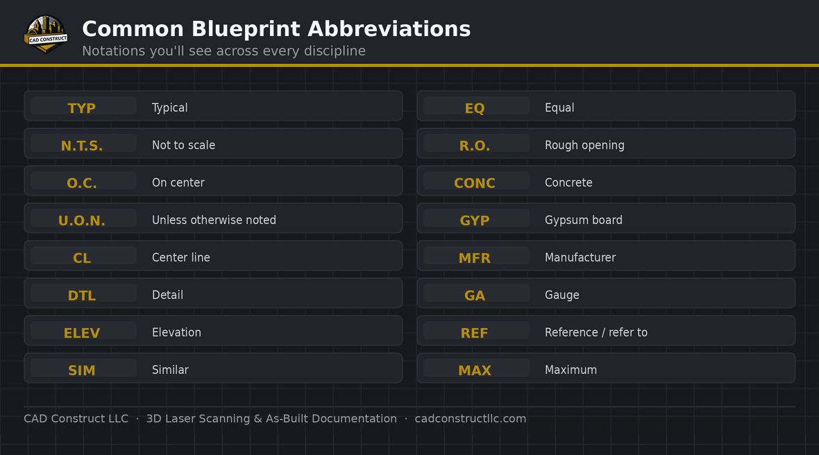
Blueprints rely on a shared visual language. Different line types carry different meanings: solid lines usually show visible edges, dashed lines show hidden or overhead elements, and center lines mark the middle of features. Symbols represent doors, windows, fixtures, electrical outlets, and more, and a legend on the drawings (or a standard symbol sheet) explains them. Abbreviations are everywhere too — for example, “GYP. BD.” for gypsum board or “T.O.W.” for top of wall.
You do not need to memorize every symbol and abbreviation at once. The key is knowing that a legend exists and referring to it whenever you encounter something unfamiliar. Over time, the common ones become second nature.
Reading dimensions and notations
Dimensions tell you the real sizes and locations of elements, shown as lines with measurements between them. Notations — the text notes scattered across a drawing — provide instructions, material callouts, and references to other sheets. Learning to follow dimension strings (the chains of measurements along a wall) and to read reference symbols that point you to related details is central to understanding a drawing fully.
A simple approach for beginners
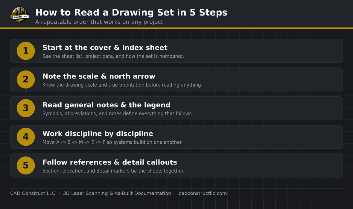
When you first pick up a set of blueprints, resist the urge to absorb everything at once. Instead, work through it methodically: start with the cover sheet and drawing index to understand the scope, read the title block on each sheet, identify what type of drawing you are looking at, note the scale, and then study the plan using the legend for any unfamiliar symbols. Follow references from one sheet to another as needed. This orderly approach turns an intimidating stack of paper into a readable story of how the building goes together.
Why reading blueprints matters
For owners and non-technical stakeholders, the ability to read blueprints is empowering. It lets you verify that a design matches your intent, catch issues before construction, communicate clearly with your builder, and understand exactly what you are paying for. For tradespeople and students, it is a foundational skill that underpins every other part of the work. And when existing drawings are missing or inaccurate, modern 3D laser scanning and as-built documentation can produce accurate, current drawings you can actually rely on.
Explore the full blueprint reading series
- Blueprint Symbols & Legends Explained
- How to Read Floor Plans
- Understanding Architectural Scale
- How to Read Elevation Drawings
- How to Read Building Section Drawings
- How to Read Site & Plot Plans
- Blueprint Dimensions & Notations Explained
- How to Read Electrical Plans & Symbols
- How to Read Plumbing Blueprints
- How to Read HVAC & Mechanical Drawings
- How to Read Structural Drawings
- Understanding the Title Block
- How to Read a Reflected Ceiling Plan
- Blueprints vs. 3D Models & BIM
Related work: See real 2D drawings and CAD deliverables in our CAD portfolio.
Frequently asked questions
Do I need special tools to read blueprints?
Not to get started. You can read most dimensions directly because they are labeled on the drawing. An architect’s scale ruler helps when you need to measure something that is not dimensioned, but understanding the organization and symbols matters more than any tool.
Why are there so many different sheets?
Each discipline — architectural, structural, mechanical, electrical, plumbing, and civil — needs its own drawings so that every trade has clear, detailed information. The letter-and-number system keeps them organized and easy to cross-reference.
What is the difference between blueprints and a 3D model?
Blueprints are 2D drawings that represent the building, while a 3D or BIM model is an intelligent three-dimensional representation. Both communicate a design; the model adds data and coordination. Our guide on
Where should a beginner start when reading a set of blueprints?
Start with the title block and sheet index to understand the project, then the floor plan for overall layout before moving into elevations, sections, and details.
What are the main types of drawings in a blueprint set?
Site/plot plans, floor plans, elevations, sections, and detail sheets, usually grouped by discipline such as architectural, structural, and MEP.
How do I know what scale a drawing uses?
The scale is noted beneath each drawing title or in the title block, for example 1/4 inch = 1 foot; use it to convert distances on the sheet to real dimensions.
Why are written dimensions more reliable than measuring the drawing?
Printed sheets can be copied or scaled at slightly wrong sizes, so always trust the written dimensions over a ruler laid on the page.
What is a revision cloud on a blueprint?
A cloud-shaped outline with a numbered triangle marks an area that changed, keyed to the revision list in the title block.
How are blueprint sheets numbered?
By discipline letter and sequence — A for architectural, S for structural, E for electrical, P for plumbing, M for mechanical — so A-101 is an architectural plan sheet.
What does the abbreviation TYP mean on a drawing?
TYP means typical — the note or detail applies to all similar conditions, so it is only drawn or labeled once.
reading blueprints vs. 3D models explores the difference in detail.
Reading construction blueprints is a learnable skill built on a consistent system. Start with the organization of the set, read every title block, learn the main drawing types, and lean on the legend for symbols. With a little practice, what once looked like chaos becomes a clear set of instructions for building.
Need accurate, current drawings of an existing building? CAD Construct LLC turns precise 3D laser scans into reliable as-built blueprints and BIM across Pittsburgh and Western Pennsylvania. Request a quote.
Common beginner mistakes to avoid
A few habits trip up people learning to read blueprints, and knowing them in advance saves confusion. The first is assuming a size instead of checking the scale or the labeled dimension — always confirm before you measure. The second is reading a single sheet in isolation; drawings constantly reference one another, so a note on a floor plan may point to a detail on another sheet that changes how you interpret it. The third is ignoring the revision history in the title block, which can mean you are working from an outdated version. And the fourth is overlooking the legend and abbreviation list, then guessing at symbols. Slowing down to cross-reference and to look things up, rather than assuming, is what separates confident blueprint reading from costly misunderstanding.
Finally, remember that blueprints describe intent, and real buildings do not always match them exactly — especially older structures that have been modified over the years. When you need to know what is truly there today, an accurate measured record such as a laser scan removes the guesswork that even a perfectly read drawing set cannot resolve.
The blueprint reading series
- USIBD Level of Accuracy (LOA), explained
- How to Read Floor Plans
- How to Read Elevation Drawings
- How to Read Building Section Drawings
- How to Read Electrical Plans & Symbols
- How to Read Plumbing Blueprints
- How to Read HVAC & Mechanical Drawings
- How to Read Structural Drawings
- How to Read a Reflected Ceiling Plan
- How to Read Site & Plot Plans
- Blueprints vs. 3D Models & BIM
- Colorized Point Clouds Explained
Turning these drawings into a field-verified digital record? See our scan-to-BIM services and as-built documentation across Pittsburgh & Western PA, or request a quote.


0 Comments