
Last updated:
Linking footings, columns and beams to the loads they carry
Key takeaways:
- Structural (S-series) sheets define the load-bearing frame.
- A column grid locates members with numbers and letters.
- Schedules specify sizes for footings, columns, and beams.
Structural drawings show the bones of a building — the foundations, framing, beams, columns, and connections that hold everything up. While architectural drawings define the spaces and appearance, structural drawings define the strength, and reading them reveals how a building resists the loads acting on it. Structural drawings use their own conventions and can look sparse and technical, but they follow a clear logic. This guide explains how to read structural drawings, from the foundation up.
Understanding structural drawings gives owners insight into how their building is built and gives students and tradespeople a foundation in one of construction’s most critical disciplines.
What structural drawings show
Structural drawings document the load-bearing system of a building. A typical structural set includes the foundation plan, framing plans for each floor and the roof, and details and schedules for the structural members. Together they define the size, location, and connection of every element that carries load — from the footings in the ground to the roof structure overhead. Where architectural drawings show finishes and layout, structural drawings strip away the appearance and show the skeleton beneath.
Structural drawings rely heavily on schedules, notes, and a grid system, and their general notes carry critical requirements, so reading them means attending to text and tables as much as to the drawings themselves.
Reading the foundation plan
The foundation plan is where a structural set usually begins, showing how the building meets the ground. It depicts footings, foundation walls, piers, and slabs — the elements that spread the building’s loads into the soil. Footing sizes and reinforcement are often given in schedules and details, and the plan shows their locations and dimensions. Reading the foundation plan tells you how the building is supported from below, which is the base on which the entire structure rests. It is the natural starting point, just as the foundation is the first thing built.
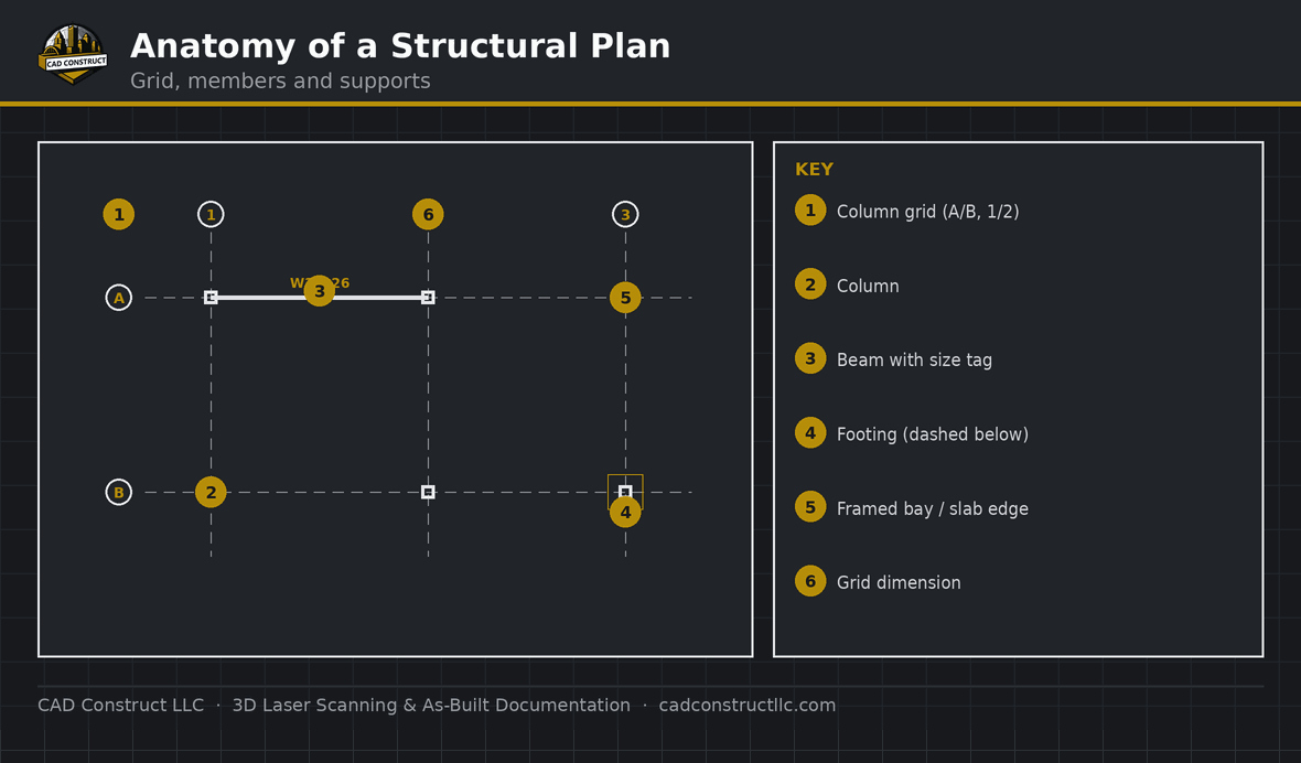
Understanding framing plans
Framing plans show the structural members that make up each floor and the roof — the beams, joists, girders, and columns that carry loads to the foundation. Members are drawn as lines with their sizes noted, and the direction and spacing of joists or trusses are indicated. A framing plan reveals how each level is supported and how loads travel through the structure down to the ground. Reading framing plans for multiple levels shows how the structural system stacks, since columns and load-bearing elements must line up between floors.
The structural grid
Most structural drawings are organized around a grid of numbered and lettered reference lines that locate columns and align the structure. This grid appears on the structural plans and is often shared with the architectural drawings, providing a common reference system for the whole building. Reading the grid tells you how the structure is organized and lets you locate any column or member precisely by its grid intersection. Understanding the grid is central to reading structural drawings, because dimensions and member locations are keyed to it.

Schedules, notes, and details
Structural drawings depend heavily on schedules, general notes, and details. Column and beam schedules list the members and their sizes; the general structural notes specify materials, design criteria, and requirements that apply throughout; and details show how members connect — how a beam meets a column, how a joist bears on a wall. Reading these together with the plans is essential, because the plans locate the members while the schedules and details define their size, material, and connection. Skipping the notes and schedules means missing much of a structural drawing’s information.
How structural drawings connect to the set
Structural drawings coordinate with the architecture (the structure must support the spaces and fit within the walls) and with the mechanical, electrical, and plumbing systems (which must route around structural members). The shared grid ties the disciplines together. Reading structural drawings alongside the others reveals how the skeleton supports and interacts with everything else. For renovations, understanding the existing structure is critical, and accurate capture through laser scanning and as-built documentation helps document structural conditions where drawings are missing.
How the S-series structural set is organized
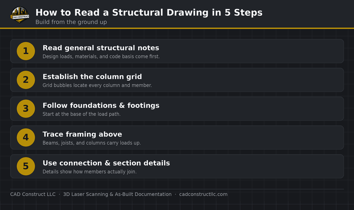
Structural drawings live in the “S” sheet series, and they follow a predictable order that makes them easier to navigate once you know it. The set almost always opens with a general structural notes sheet — often S0 or S1 — that carries design loads, material strengths, code references, and the abbreviations used throughout. From there the drawings move down through the building: foundation plan first, then framing plans for each level, then roof framing, followed by structural sections, connection details, and the schedules that size every footing, column, and beam.
Because the general notes govern the entire set, they are worth reading before any individual plan. A single note about concrete strength, rebar cover, or a required special inspection can change how you interpret every detail that follows. When a framing plan points to a detail with a section cut, the reference bubble tells you exactly which sheet and detail number to turn to for the connection.
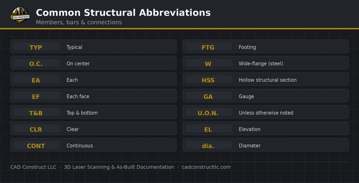
Structural abbreviations and symbols to know
Structural drawings are deliberately terse, so a handful of abbreviations unlock most of the information. You will see TYP for typical, EA for each, EW for each way, EF for each face, OC or C/C for on-center spacing, and CONT for continuous. Steel members are called out by shape and size — a designation like W12x26 describes a wide-flange beam roughly 12 inches deep weighing 26 pounds per foot — while concrete reinforcing is noted by bar size, such as #5 bars at 12″ on center.
Symbols carry just as much meaning as the notes. A column is often shown as a solid shape at a grid intersection, a beam as a heavy line spanning between supports, and a section cut as a bold arrow pointing in the direction of view. Learning to read the grid callouts alongside these symbols lets you locate any member in the building by its column line and gridline coordinates.
Common mistakes when reading structural drawings
The most common misread is treating the structural plan like an architectural one and expecting to see walls, finishes, and rooms — structural sheets intentionally strip all of that away to show only what carries load. Another is skipping the general notes and missing a project-wide requirement, such as a minimum lap splice length or a special inspection. A third is reading a beam or column size off the plan without cross-checking the schedule and the connection detail, which together define how the member is actually built and fastened.
How laser scanning verifies existing structure before you build
On renovations, additions, and adaptive-reuse projects, the structure you are tying into rarely matches the original drawings. Beams sag, columns shift, and decades of modifications go undocumented. A 3D laser scan records the existing framing exactly as it stands today, giving engineers accurate member locations, elevations, and clearances to design against. Turning that scan into a scan-to-BIM model lets the structural team verify fit before steel is ordered or connections are detailed.
That field-verified baseline prevents the costly surprises that show up when new structure meets an existing building that was never quite built to plan. If you are documenting an existing structure for a renovation, CAD Construct can capture it first — contact us or see our pricing to plan the scope.
Related blueprint reading guides
- How to Read Construction Blueprints
- How to Read Building Section Drawings
- How to Read Site & Plot Plans
- Blueprint Dimensions & Notations Explained
Related work: See real 2D drawings and CAD deliverables in our CAD portfolio.
Frequently asked questions
Why do structural drawings look so sparse?
Structural drawings focus only on the load-bearing system, leaving out finishes, fixtures, and other details shown elsewhere. This keeps them clear and focused on structure, but it means much of their information lives in the schedules, notes, and details rather than in a dense drawing — so reading those is essential.
What is a structural grid?
A structural grid is a system of numbered and lettered reference lines that locate columns and organize the structure. Shared across the drawing set, it gives every discipline a common way to reference locations, so a column at grid B-3, for example, means the same thing on every sheet.
How do I know the size of a beam or column?
Member sizes are usually noted on the framing plan beside each member and defined more fully in beam and column schedules. Reading the plan tells you where a member is, and the schedule tells you its exact size, material, and sometimes its connections.
Structural drawings reveal the skeleton of a building — the foundations, framing, and connections that carry every load to the ground. Read them from the foundation up, follow the grid, and pair the plans with their schedules, notes, and details, and the structure that holds a building together becomes clear.
<
p class=”post-cta”>
Do structural drawings always match the existing building?
Not always — especially in older or heavily modified buildings, where the as-built structure can differ noticeably from the original drawings. Beams may have been reinforced, columns relocated, or openings cut without a record. A field-verified 3D laser scan is the most reliable way to confirm real member sizes, locations, and elevations before you design or fabricate anything new against them.
What are structural drawings?
The S-series sheets showing foundations, footings, columns, beams, and framing that carry the building’s loads.
What is a column grid?
A network of numbered and lettered reference lines that locates columns and structural members consistently across all sheets.
What is a foundation plan?
A top-down drawing of footings, foundation walls, and slabs showing sizes, depths, and reinforcement.
How are beams and columns labeled?
With callouts like W12x26 for a steel wide-flange, or a mark keyed to a schedule that gives the full size and details.
What is a framing plan?
A plan showing the floor or roof structure — joists and beams — with their spacing and direction.
What is rebar and how is it shown?
Reinforcing steel in concrete, noted by bar size and spacing, for example #5 bars at 12 inches on center.
Related blueprint reading guides
- USIBD Level of Accuracy (LOA), explained
- How to Read Construction Blueprints — full guide
- How to Read a Reflected Ceiling Plan
- How to Read Site & Plot Plans
- How to Read Floor Plans
- How to Read Elevation Drawings
- Blueprints vs. 3D Models & BIM
Turning these drawings into a field-verified digital record? See our scan-to-BIM services and as-built documentation across Pittsburgh & Western PA, or request a quote.


0 Comments