
Last updated:
Where lights, diffusers and grid meet a ceiling mirrored onto the floor
Key takeaways:
- An RCP shows the ceiling reflected downward, viewed from above.
- It locates lights, HVAC diffusers, grid, and ceiling heights.
- It keeps overhead trades coordinated in one view.
A reflected ceiling plan, almost always shortened to RCP, is one of the more confusing drawings for newcomers because it shows the ceiling — but drawn as if you were looking down at it, not up. Understanding that single idea is the key to reading it correctly, and once it clicks, the RCP becomes one of the most useful sheets in the set for coordinating lighting, HVAC, and ceiling design.
This guide explains what a reflected ceiling plan is, why it is drawn the way it is, what symbols and information it contains, and how it coordinates with the other drawings in a construction set. Whether you are planning a renovation, reviewing a design, or just trying to make sense of a set of plans, learning to read the RCP will help you understand everything that happens overhead.
What “reflected” actually means
The name sounds technical, but the concept is simple. Imagine placing a large mirror on the floor of a room and looking down into it. The reflection would show you the ceiling above, but with the same left-to-right orientation as the floor plan you are standing on. That is exactly what a reflected ceiling plan does: it depicts the ceiling as if it were reflected downward onto the floor, so it lines up with the floor plan instead of being flipped.
This matters because it keeps everything consistent. A light fixture shown in the northeast corner of the RCP is in the northeast corner of the actual room. If ceilings were simply drawn “looking up,” left and right would reverse and coordinating fixtures with walls and furniture below would be a constant source of error. The reflected convention removes that confusion entirely.
What a reflected ceiling plan shows
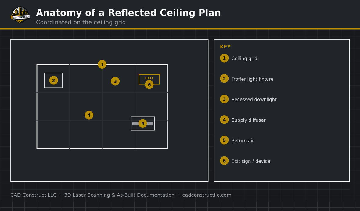
An RCP documents everything that lives on or in the ceiling. That includes the ceiling grid for suspended acoustical tile systems, light fixtures of every type, HVAC diffusers, registers, and return grilles, sprinkler heads, smoke detectors and speakers, access panels, and changes in ceiling height or material. It also shows soffits, bulkheads, and coffers — any three-dimensional shaping of the ceiling plane.
What the RCP deliberately leaves out is just as important. You will not see furniture, floor finishes, or anything below eye level, because those belong on other sheets. By stripping the drawing down to ceiling elements only, the RCP gives designers a clean canvas to lay out a coordinated, symmetrical ceiling without the clutter of the floor plan competing for attention.
Reading the ceiling grid and fixture layout
In commercial spaces, the most prominent feature of an RCP is the ceiling grid — the network of lines representing a suspended tile system, typically laid out in 2×2 or 2×4 foot modules. Designers use this grid as a coordinating framework: light fixtures, diffusers, and other elements are usually aligned to it so the finished ceiling looks orderly rather than random. Reading the grid tells you how the ceiling is organized and where each element is meant to fall.
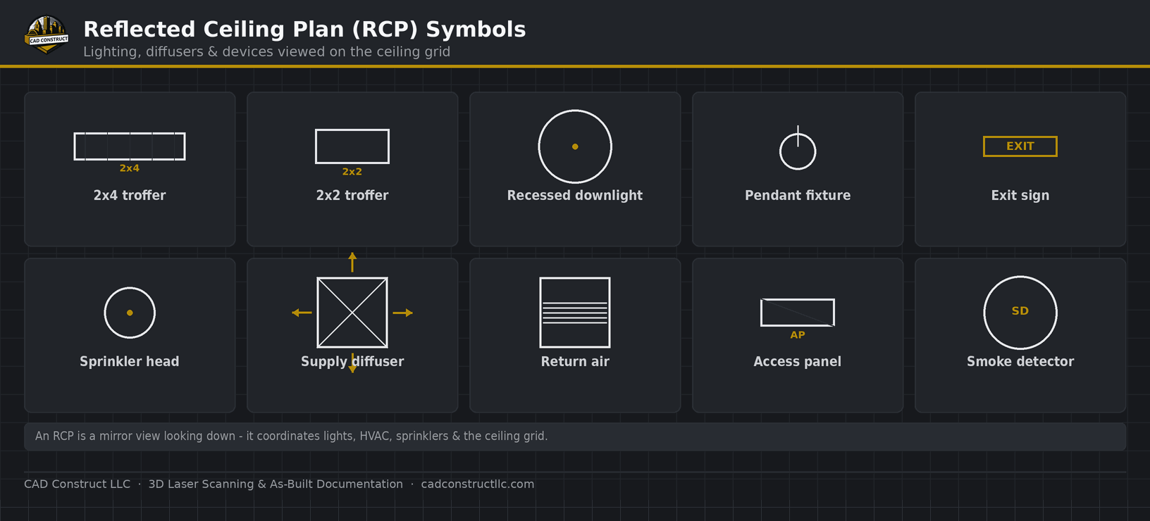
Fixtures are shown with standardized symbols and keyed to a lighting legend, much like other disciplines. A recessed troffer, a downlight, a pendant, and an exit sign each have their own symbol, and a fixture schedule ties those symbols to specific manufacturers and model numbers. Because lighting appears here and also relates to the electrical plans, the two sheets must be read together to understand both the placement and the wiring of every fixture.
How the RCP coordinates with other trades
The ceiling is crowded real estate. Lighting, mechanical, fire protection, and audiovisual systems all compete for the same plane, which makes the RCP one of the most important coordination drawings in the set. A diffuser shown on the mechanical drawings must land in a location that works with the light fixtures on the RCP, and both must avoid sprinkler heads and structural beams above.
When these elements are not coordinated on paper, they collide in the field — a light fixture lands where a duct needs to run, or a sprinkler head ends up in the middle of a ceiling tile instead of centered. Reading the RCP alongside the mechanical, electrical, and structural sheets is how designers catch those conflicts before construction, and it is exactly the kind of coordination that a 3D model makes far easier to verify.
Ceiling heights, materials, and finishes
Beyond fixtures, the RCP communicates the shape and finish of the ceiling itself. Ceiling height is typically noted with an elevation tag — for example, a note reading 9’-0” AFF means the ceiling sits nine feet above the finished floor. Where the ceiling steps up or down, the RCP marks the transition and tags each height, and material callouts identify whether an area is gypsum board, acoustical tile, wood, or an open structure left exposed.
These notes let a contractor build the ceiling exactly as designed, and they let a client understand how a space will feel — a coffered nine-foot ceiling reads very differently from a flat eight-foot one. Reading the height and material callouts together gives you the full three-dimensional picture that a flat plan alone cannot.
Why field-verified ceilings matter in renovations
In existing buildings, what is actually above the ceiling rarely matches old drawings. Ducts, conduit, and structure have been modified over the years, and the available plenum space is often tighter than expected. Capturing the space with a 3D laser scan and building a scan-to-BIM model gives designers an accurate, coordinated basis for a new reflected ceiling plan — so new lighting and mechanical actually fit.
If you are renovating a space and need reliable existing-condition documentation before designing a new ceiling, CAD Construct can help. Contact us or review our pricing to plan the scan.
Common RCP symbols and abbreviations
Like every discipline, the reflected ceiling plan relies on a legend to keep the drawing uncluttered. Lighting symbols do the heaviest lifting: a recessed troffer is often shown as a rectangle with an X or grid pattern, a downlight as a small circle, a wall washer as a half-symbol against a wall, and an emergency or exit fixture with its own distinct marker. Each symbol ties back to a fixture type — frequently labeled with a letter such as Type A, Type B, and so on — that the fixture schedule then matches to a specific product.
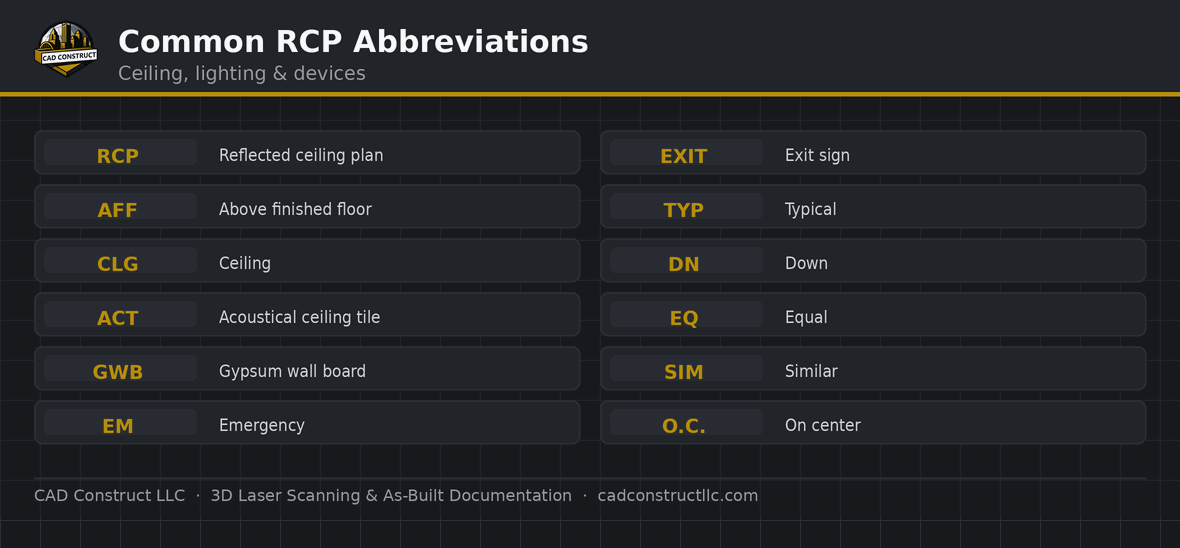
Abbreviations round out the picture. You will commonly see AFF for above finished floor, ACT for acoustical ceiling tile, GWB or GYP for gypsum wall board, EM for emergency, and CL for centerline. Reading the legend and abbreviations first means you spend your time understanding the ceiling design rather than decoding shorthand. When a symbol appears that is not in the legend, that is usually a sign to check for a supplementary note or a related detail sheet.
Tips for reviewing a reflected ceiling plan
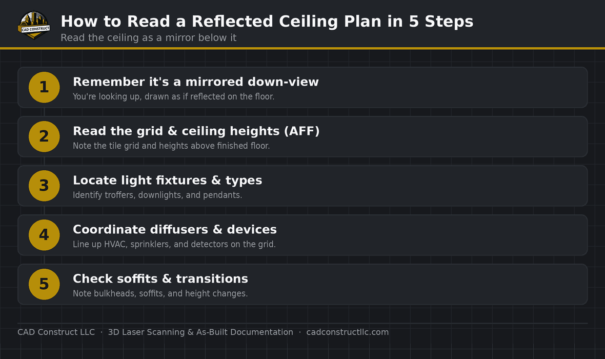
When you review an RCP, work in a deliberate order rather than scanning at random. Start by confirming ceiling heights and any changes in elevation, since those set the vertical framework for everything else. Next, check that fixtures and diffusers align to the ceiling grid and are spaced symmetrically — a well-designed ceiling looks intentional, and misaligned elements often signal a coordination problem. Then verify that lighting, mechanical, and fire-protection elements are not competing for the same spot.
Finally, cross-reference the RCP against the other disciplines. Confirm the lighting matches the electrical plans, the diffusers match the mechanical drawings, and nothing conflicts with structure overhead. This habit catches the overhead clashes that are expensive to fix once the ceiling is being installed. For the bigger picture of how all these sheets fit together, see our overview of how to read construction blueprints, which walks through an entire set from cover to details.
Related blueprint reading guides
- How to Read Construction Blueprints
- How to Read Electrical Plans & Symbols
- How to Read HVAC & Mechanical Drawings
- How to Read Floor Plans
Related work: See real 2D drawings and CAD deliverables in our CAD portfolio.
Frequently asked questions
Why is it called a reflected ceiling plan?
Because the ceiling is drawn as if reflected in a mirror lying on the floor. This keeps the ceiling’s orientation aligned with the floor plan below, so elements do not appear reversed left-to-right.
What is the difference between a floor plan and an RCP?
A floor plan shows everything at floor level — walls, doors, furniture — as if the roof were removed and you looked down. An RCP shows only the ceiling above, drawn in the same orientation, including lighting, diffusers, grid, and ceiling heights.
What does AFF mean on a reflected ceiling plan?
AFF stands for “above finished floor.” A ceiling height noted as 9’-0” AFF means the ceiling is nine feet above the completed floor surface, which is the standard reference point for vertical dimensions.
Who uses the reflected ceiling plan?
Architects, electricians, HVAC installers, fire-protection contractors, and general contractors all rely on the RCP. It is the single drawing that coordinates lighting, mechanical, and life-safety systems across the ceiling plane, so nearly every trade working overhead references it before and during installation.Read the reflected ceiling plan alongside the floor plan and the mechanical and electrical sheets, and the space above your head stops being a mystery: you can see exactly how lighting, air, and life-safety systems come together overhead before a single fixture is hung.
What is a reflected ceiling plan?
A plan showing the ceiling mirrored onto the floor and viewed from above, mapping lights, grid, diffusers, and ceiling features.
Why is it called reflected?
Because the ceiling is imagined reflected down onto the floor, so its layout aligns with the floor plan’s orientation.
What appears on an RCP?
Light fixtures, HVAC diffusers, ceiling grid, soffits, bulkheads, sprinklers, and ceiling height notes.
How does an RCP differ from a floor plan?
A floor plan looks down at the floor, while an RCP represents what is overhead, so walls are shown but floor items are not.
What is a ceiling grid?
The suspended acoustic-tile framework, drawn to show the module layout and how it centers in the room.
How are ceiling heights shown?
With notes such as AFF (above finished floor) heights at each ceiling area, or a heights legend.
Related blueprint reading guides
- USIBD Level of Accuracy (LOA), explained
- How to Read Construction Blueprints — full guide
- How to Read Site & Plot Plans
- How to Read Floor Plans
- How to Read Elevation Drawings
- How to Read Building Section Drawings
- Blueprints vs. 3D Models & BIM
Turning these drawings into a field-verified digital record? See our as-built documentation and 3D laser scanning in Pittsburgh across Pittsburgh & Western PA, or request a quote.


0 Comments