Last updated:
Key takeaways:
- Plumbing plans cover supply, drainage, waste, and venting.
- Line types distinguish hot, cold, waste, and vent piping.
- Riser diagrams show the system vertically across floors.
Plumbing blueprints show how water and waste move through a building — the supply lines that bring clean water in, the drainage that carries waste out, and the vents that keep the system working. Plumbing drawings have their own symbols, line types, and conventions, and reading them reveals a system that is largely hidden in the finished building. This guide explains how to read plumbing blueprints so you can understand a building’s water and waste systems.
Whether you are an owner, a tradesperson, or a student, learning to read plumbing drawings demystifies one of a building’s most essential systems.
What plumbing drawings show
Plumbing drawings document the pipes, fixtures, and equipment that supply water and remove waste. They typically include plumbing floor plans showing fixture and pipe layouts, and riser diagrams or isometric drawings showing the system in a schematic vertical view. Together they communicate where every fixture is, how it connects to supply and drainage, and how the whole system is organized. Because plumbing is mostly concealed inside walls, floors, and chases, these drawings are the primary way to understand it.
As with other technical drawings, plumbing plans rely on a legend that defines the symbols and line types used, which is the starting point for reading them.

Understanding plumbing line types
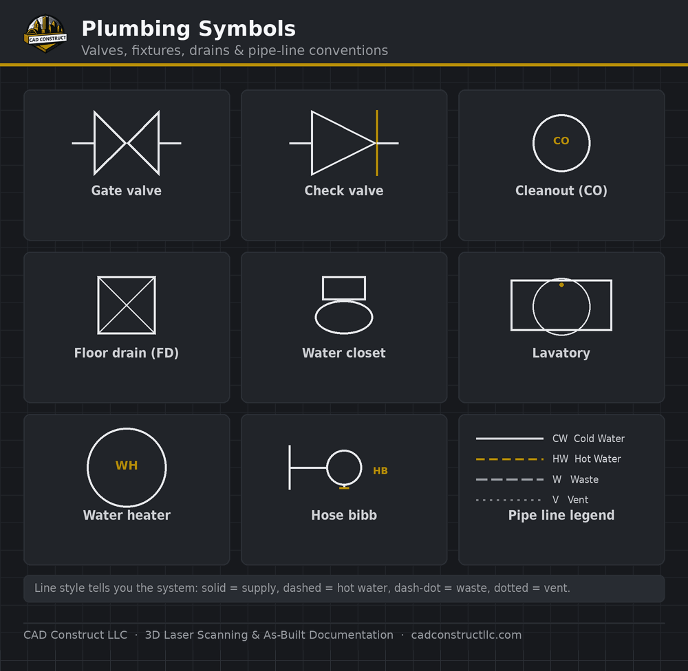
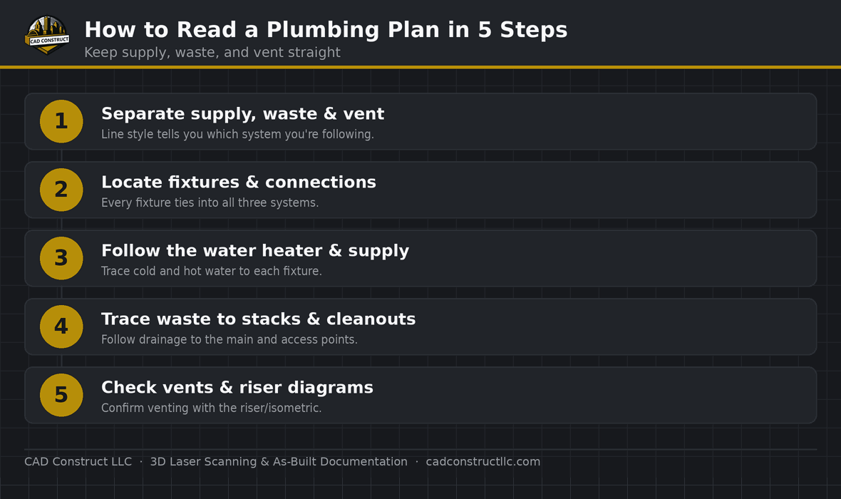
The most important convention in plumbing drawings is the use of different line types for different systems. Cold water, hot water, waste (or sanitary) lines, vent lines, and gas lines are each drawn with a distinct line style — solid, dashed, or patterned — so you can trace each system separately even where pipes cross. Learning these line types is the key to reading plumbing plans, because the same route may carry supply above and drainage below, and the line types tell them apart. The legend defines exactly which style means which system.

Common plumbing symbols
Plumbing drawings use symbols for fixtures, fittings, and valves:
- Fixtures — sinks, toilets, tubs, showers, water heaters, and floor drains, each with a recognizable symbol.
- Valves — shut-offs, check valves, and control valves, shown with small standardized marks on the lines.
- Fittings — elbows, tees, and connections where pipes join or change direction.
- Cleanouts — access points in the drainage system for maintenance.
- Meters and backflow preventers — where the building connects to the water supply.
Recognizing these symbols, together with the line types, lets you read how water reaches each fixture and how waste drains away.
Reading supply and drainage systems
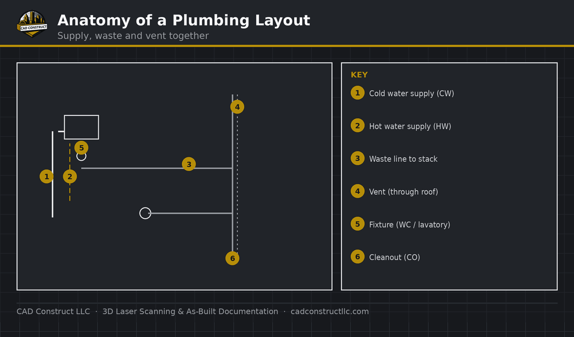
A plumbing system has two main halves, and reading them separately clarifies the whole. The supply side brings pressurized hot and cold water from the source to each fixture, branching through the building. The drainage side (drain-waste-vent, or DWV) carries waste away by gravity and uses vents to maintain proper pressure so traps seal correctly. On the plan, following the supply lines to a fixture and the drainage lines from it shows the complete path of water through that fixture. Understanding this two-part logic is central to reading plumbing drawings.
Riser diagrams and isometrics
Because plumbing runs vertically through a building, floor plans alone cannot show the full system. Riser diagrams and plumbing isometrics provide a schematic, often three-dimensional view of how pipes run between floors and connect the fixtures throughout the building. These diagrams are not to scale but show the system’s connectivity and vertical organization clearly. Reading them alongside the plans gives you a complete understanding of how the plumbing works from the water main to the highest fixture and down through the drains.
How plumbing plans connect to the set
Plumbing drawings coordinate with the architectural plans (which locate the fixtures and the spaces), the structural drawings (since pipes must route around framing), and the mechanical drawings (as systems share ceiling and chase space). Reading them together ensures the plumbing fits and functions. For renovations, accurate documentation of existing plumbing supports planning, and laser scanning and as-built documentation help capture concealed and existing conditions where drawings are missing.
Related blueprint reading guides
- How to Read Construction Blueprints
- How to Read Electrical Plans & Symbols
- How to Read HVAC & Mechanical Drawings
- Blueprint Symbols & Legends Explained
Related work: See real 2D drawings and CAD deliverables in our CAD portfolio.
Frequently asked questions
How do I tell hot water from cold water on a plumbing plan?
Different line types distinguish them — hot and cold water lines are drawn with distinct styles defined in the legend. Consulting the legend and then tracing each line style separately lets you follow the hot and cold supply through the building even where lines cross.
What is a riser diagram?
A riser diagram is a schematic, not-to-scale drawing showing how plumbing runs vertically through a building and connects the fixtures across floors. It complements the floor plans by revealing the vertical organization that a top-down plan cannot show.
What does DWV mean?
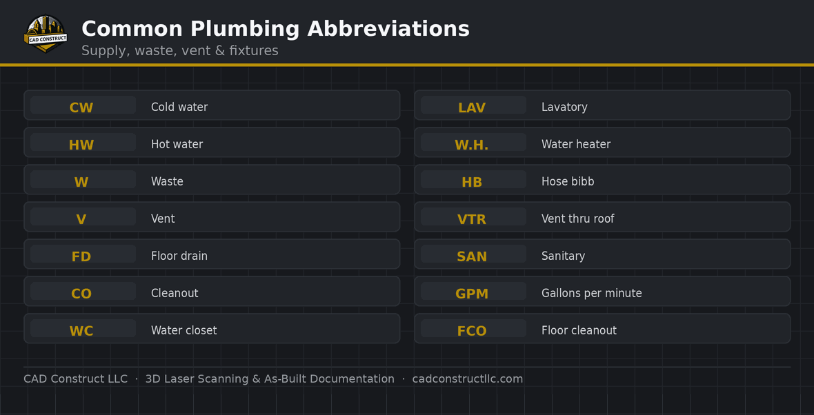
DWV stands for drain-waste-vent, the part of the plumbing system that removes waste by gravity and uses vents to maintain the air pressure that lets drains flow and traps seal. Reading the DWV lines shows how waste leaves each fixture and the building.
Plumbing blueprints reveal a building’s hidden water and waste systems through symbols, line types, and riser diagrams. Learn the line types that distinguish supply, drainage, and vent, recognize the fixture and valve symbols, and read the risers alongside the plans, and the concealed plumbing of a building becomes clear.
Why are vents part of a plumbing system?
Vents allow air into the drainage system so that waste flows smoothly and the water seals in fixture traps are not siphoned away. Without proper venting, drains gurgle, empty slowly, and can allow sewer gas into the building. On the plans, vent lines are drawn with their own line type, and reading them shows how the system maintains the air pressure that makes drainage work.
Where do I find plumbing information on a small project?
On smaller residential projects, plumbing may be shown on the architectural floor plans with fixtures indicated and minimal piping, relying on the plumber to route the system to code. Larger and commercial projects have dedicated plumbing sheets with full plans, riser diagrams, and schedules. Knowing which to expect helps you find the plumbing information you need for a given project.
Can plumbing be documented for a building without drawings?
Yes, to the extent it is visible. Exposed piping, fixtures, and equipment can be captured and documented to create accurate records of the existing plumbing. While concealed pipes cannot be seen without investigation, documenting the visible system and the fixture layout gives renovation and facility teams a dependable starting point rather than assumptions.
What is a plumbing plan?
A drawing showing the location of fixtures and the supply, drain, waste, and vent piping that serves them, using standard symbols.
What do the different pipe line types mean?
Distinct line styles separate hot water, cold water, waste, and vent lines; the legend defines each one.
What is the difference between supply and DWV?
Supply lines bring pressurized hot and cold water, while DWV — drain, waste, vent — carries wastewater out and lets the system breathe.
Why are vents important on plumbing drawings?
Vents equalize pressure so traps hold water and drains flow properly; the plans show their required routing.
Related blueprint reading guides
- USIBD Level of Accuracy (LOA), explained
- How to Read Construction Blueprints — full guide
- How to Read HVAC & Mechanical Drawings
- How to Read Structural Drawings
- How to Read a Reflected Ceiling Plan
- How to Read Site & Plot Plans
- Blueprints vs. 3D Models & BIM
Turning these drawings into a field-verified digital record? See our as-built documentation and 3D laser scanning in Pittsburgh across Pittsburgh & Western PA, or request a quote.


0 Comments