
Last updated:
Connecting the footprint, setbacks and utilities to the lot they sit on
Key takeaways:
- A site plan shows the whole property from above, not the interior.
- It covers boundaries, setbacks, utilities, and grading.
- It is drawn at an engineering scale to fit the larger area.
Before a building takes shape, it has to sit somewhere — and the drawing that shows where and how is the site plan. Site plans (and the closely related plot plans) present an aerial view of the entire property, showing the building’s placement, the boundaries of the lot, and everything around the structure. Learning to read a site plan is essential for understanding how a project relates to its land, its neighbors, and the rules that govern it. This guide explains how to read site and plot plans.
If floor plans show the inside of a building, site plans show its place in the world.
What a site plan shows
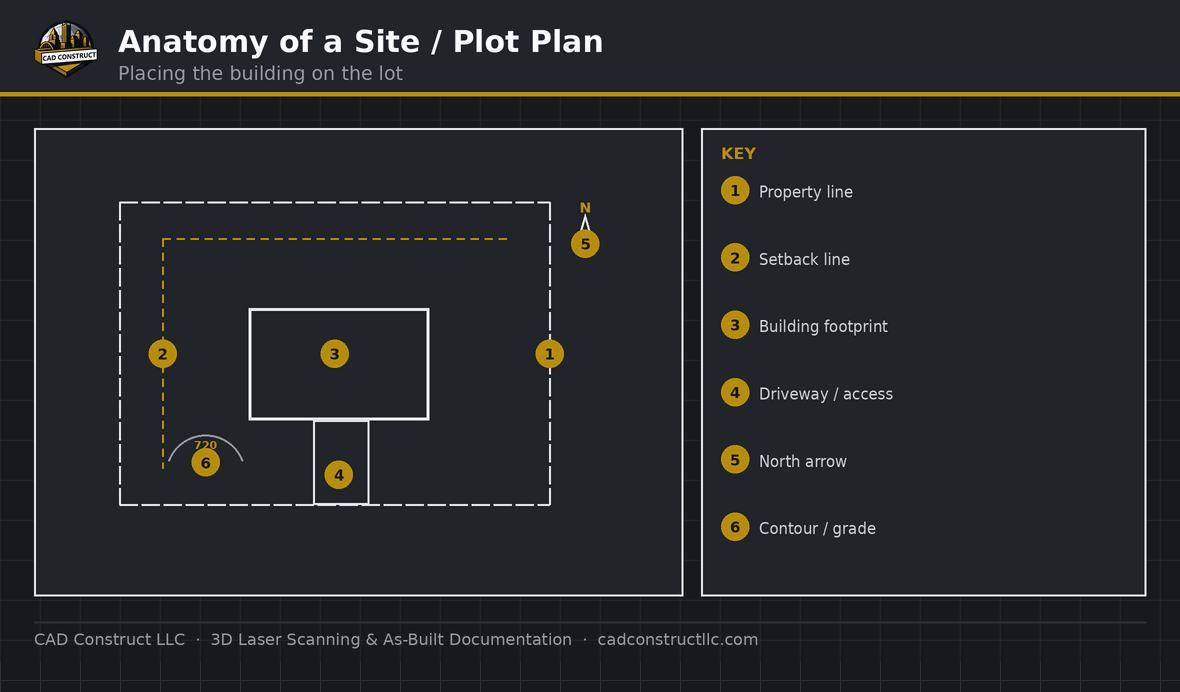
A site plan is a scaled, top-down drawing of an entire property, viewed from above as if looking down from the sky. It shows the outline of the building on the lot, the property boundaries, and the features of the site around the structure. Where floor plans zoom into the building, the site plan zooms out to show the whole parcel. A plot plan is a similar drawing, often simpler, focused on the placement of the building and required setbacks; the terms overlap and are sometimes used interchangeably.
Because it covers a large area, a site plan is usually drawn at an engineering scale such as 1" = 20′ or 1" = 30′, rather than the architectural scales used for building plans.

What you will find on a site plan
Site plans pack in a range of information about the property and how the building relates to it:
- Property lines and the dimensions of the lot, defining the legal boundaries.
- The building footprint and its position on the lot.
- Setbacks — the required distances between the building and the property lines.
- Driveways, walkways, parking, and paving.
- Utilities such as water, sewer, gas, and electrical connections.
- Grading and drainage, often shown with contour lines and spot elevations.
- Landscaping, trees, and site features.
- A north arrow and often a scale bar.
Reading these together tells you how the building fits its site, how people and vehicles reach it, and how the land is shaped and drained around it.

How to read a site plan step by step
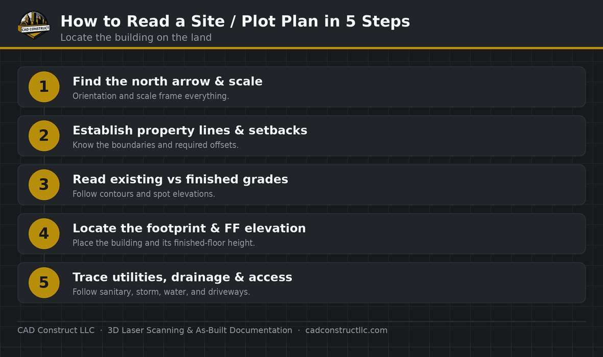
Start with the title block and the scale, remembering that site plans usually use an engineering scale. Find the north arrow to orient yourself. Then trace the property lines to understand the shape and size of the lot, and locate the building footprint within it. Read the setback dimensions between the building and the property lines. Follow the driveways, walks, and parking to understand access, and note the utility connections. Finally, study the grading and drainage information to see how the land slopes. Working from the boundaries inward gives you a clear picture of the whole site.
Understanding property lines and setbacks
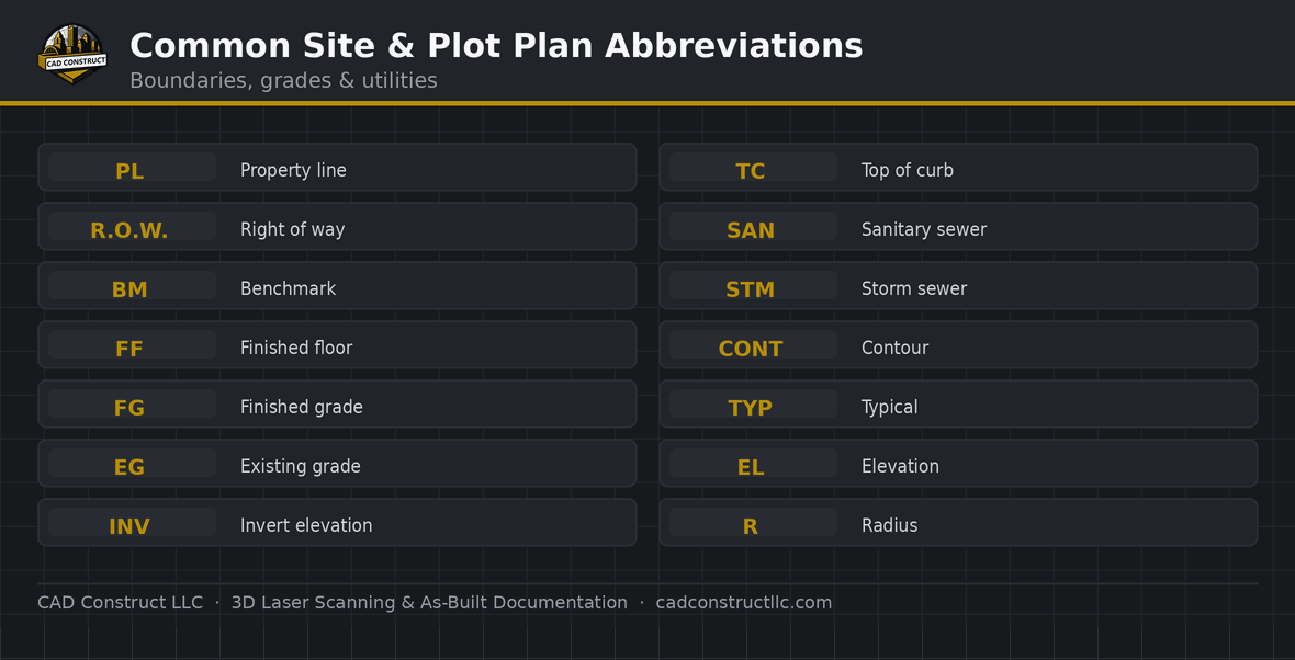
Property lines define the legal edges of the lot, and their lengths and bearings are shown on the plan. Setbacks are the minimum distances that zoning requires between the building and each property line — front, sides, and rear. Reading the setback dimensions tells you whether the building is placed legally and how much open space surrounds it. These figures are central to any project because they govern where a building can go, and they are among the first things a reviewer checks. Understanding them lets you see the constraints the design had to work within.
Reading grading and drainage
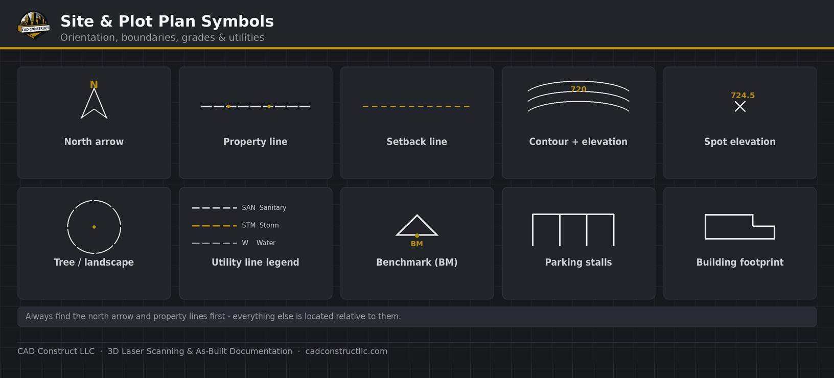
Site plans often show how the land is shaped through contour lines — curving lines that connect points of equal elevation — and spot elevations that give exact heights at specific points. Reading contours tells you how the ground slopes: lines close together mean steep terrain, lines far apart mean gentle slopes. Drainage arrows and elevations show how water is directed away from the building. This information matters because proper grading protects a building from water, and reading it helps you understand how the site manages runoff.
Utilities and site connections
A site plan shows how the building connects to municipal or on-site utilities — water and sewer lines, gas, electrical service, and stormwater systems — often with lines running from the building to the street or to on-site systems. Reading these tells you how the building is serviced and where connections are made. On projects involving site work, these utility routes are important for coordination, and understanding them rounds out your picture of how the building functions within its infrastructure.
How site plans relate to the rest of the set
The site plan is usually part of the civil drawings and sets the context for the architectural set that follows. It establishes the building’s position, orientation, and relationship to the land, which the floor plans and elevations then develop in detail. Reading the site plan first gives you the big-picture context for everything else. When a property’s existing conditions must be captured accurately — boundaries, structures, and topography — 3D laser scanning and survey methods produce precise site documentation that supports design and as-built records.
Related blueprint reading guides
- How to Read Construction Blueprints
- How to Read Floor Plans
- Blueprint Dimensions & Notations Explained
- How to Read Structural Drawings
Related work: See real 2D drawings and CAD deliverables in our CAD portfolio.
Frequently asked questions
What is the difference between a site plan and a plot plan?
The terms overlap and are sometimes used interchangeably. A site plan is generally a detailed drawing of the whole property including grading, utilities, and site features, while a plot plan is often a simpler drawing focused on the building’s placement and setbacks. Both show the property from above.
Why are site plans drawn at engineering scales?
Because they cover large areas — an entire lot rather than a single building — engineering scales like 1" = 20′ or 1" = 30′ let the whole property fit on a sheet while keeping measurements readable. Building plans use architectural scales for finer detail.
What are contour lines?
Contour lines connect points of equal elevation to show the shape of the land. Lines close together indicate steep slopes; lines spaced far apart indicate gentle terrain. They let you read how a site rises and falls across the property.
The site plan shows a building in its place — the lot, the boundaries, the setbacks, the access, and the shape of the land. Read it from the property lines inward, orient yourself with the north arrow, and study the grading and utilities, and you will understand how a project relates to the ground it stands on.
What is a north arrow and why does it matter?
The north arrow indicates the compass orientation of the drawing, which matters because it tells you how the building faces the sun, the street, and the surrounding site. Orientation affects daylight, views, and how the plan relates to the real world, so finding the north arrow is one of the first steps in reading any site plan or floor plan.
Can a site plan be created for an existing property without drawings?
Yes. When no current site documentation exists, a measured survey — including capture of existing structures, boundaries, and topography — can produce an accurate site plan. This is especially valuable for renovations and additions, where the placement of new work depends on knowing exactly where the existing building and property lines are.
What is a site plan?
A top-down drawing of the whole property showing the building footprint, lot lines, setbacks, driveways, utilities, and landscaping.
What is a setback?
The minimum required distance between a building and the property line, set by zoning and shown on the site plan.
What scale are site plans drawn at?
Usually an engineering scale in decimal feet, such as 1 inch = 20 feet, to fit the entire lot on the sheet.
What do contour lines mean on a site plan?
They connect points of equal elevation to show the land’s slope; closely spaced lines indicate steeper ground.
What is a property line?
The legal edge of the lot, typically shown with bearings and distances taken from a survey.
Related blueprint reading guides
- USIBD Level of Accuracy (LOA), explained
- How to Read Construction Blueprints — full guide
- How to Read Floor Plans
- How to Read Elevation Drawings
- How to Read Building Section Drawings
- How to Read Electrical Plans & Symbols
- Blueprints vs. 3D Models & BIM
Turning these drawings into a field-verified digital record? See our 3D laser scanning in Pittsburgh and scan-to-BIM services across Pittsburgh & Western PA, or request a quote.


0 Comments